Sunday 8 May 2011

Door Pictures and Brief History of my Door

The Concept:

My door and my first demographic drawing of its layout and size to my door, this would need history to give it that personal touch making it come to life and things that start very simple get complicated very quick as the history of art teaches us, art starts with a shape and grows to looked out of control but this is how all concept ideas take shape.

My drawing I've added a few touches of personality the (P.A.N.S-S5) Palm analyse nanotechnology scanner series 5, this deals with human DNA this is the only way in through the door, as no aliens are allowed beyond this point for what lies beyond the door deals with (Bacteria Hazards) this is one of several doors, and the game that I would make, would be about BH 53 this is what I called my door.

I start with a hi poly version of my door transporting into mud box for hard surface modelling this is where I added my scratches and dents and rust indentations to give it a lot of character.


In figure 1 this was my palm scanner I got this idea to use this technology, from a documentary about future scanning using nanotechnology.

In figure 2, I did a foot pressure pad, which tells the scanner on the door there's somebody standing there? I also gave this a translucent dirt layer.
In figures 4, 5 &6 these are assets for the door alarms and lighting.


I did this picture in Photoshop to show how the nanotechnology reacts to human DNA; the blue ones deal with adrenaline levels and blood pressure. The red ones deal with blood and high stress and awareness.

The green ones deal with skin and the texture, and the grey ones are redundant backup.
In my last picture I put all my textures together on the separate parts of the door to give it that final look. I really enjoyed doing the door it taught me some good techniques within Maya Autodesk and Photoshop putting all the techniques together to end with the finished product for a game ready asset, I've already tried my door in UDK.


My door is now a game ready asset and there is a lot still to learn about UDK transporting maps plugging them into the right coordinates so they appear on your door within the games workspace.

         A UDK is a solid piece of technological; I’m still trying to learn as much as I can.

Rigging with a Twist


• File Structure


When start a new project the file system must be sound and correct to allow for a good workflow.
This will hold true for any type of construction pipeline and naming conversion within character creation.

• CharacterNode01
• Grp_MODEL01
• Grp_globalMove01
• Grp_BONES01
• Grp_extraNodes01
• Grp_IK01
• Grp_controlObjects01
• Grp_cl_spine01

This would be my typical naming construction for my new character rig
On starting a new naming pipeline within my workflow, and helping me to get a good end result by starting with these eight files.
Character node; this file keeps the work area neat with a collapsible file system.

• GRP

All files will be stored as group nodes; for later use with skeletal structure and easy parenting of bones.
All my files will end with (01) as this lets me know it’s part of the main character project, not an asset like (armour, guns etc.) this would all end with (02).

• Bone Formation


On starting my new skeletal structure the first bones laid will be the left leg, from hip to toe, the new formation of bones will be named.

• Bn_l_hip01
• Bn_l_knee01
• Bn_l_ankle01
• Bn_l_ball01
• Be_l_toe01

All (bn) is for bones, named like this for the sole purpose of binding to the skin at the end of rigging.
This go’s for (be) that stands for bone end, named like this so it will not be bound to the skin also at the end of the rigging.
On setting my bones for left leg I will now check the orientation point of my joints to make sure (Y) is all in the same direction.
When the right leg is mirrored from the left leg, the (Y) will look the wrong way round but this is normal the bone chain.
At this point I will now set my (IK) handles from hip two ankles, on both legs. [1]


 • IK Handles


There are three types of (IK) handles; they each have a role to play in a character rig.

• IKRPSolver
• IKSCSolver
• IK Spline Handel

How they are defined; ikRPSolver (Rotate Plane), ikSCSolver (Single Chain) and also the IK Spline Handle.
The Rotate Plane IK Solver is the default IK Solver and is probably used the most when setting up characters; it is most useful when used in conjunction with chains in joints such as an arm (where the elbow will need to be rotated into place) or a leg (where the knee will need to be rotated into place). It essentially has the ability to control the twisting direction of the chain that it is controlling.
Also if you are adding a (Pole Vector) with a control object to your characters knees, or elbows, this will not work with an ikSCSolver (Single Chain).
As a single chain an (ikSCSolver) is best used in bones that have no need for an outside controlling influence. [1] In this case, it best served me in a reverse foot lock on my leg rig.

• IK Spline Handle


The IK Spline Handle is actually quite a powerful handle, it is best used when you would have a complex series of joints, for example a characters spine; or a character who has a tail, in both cases you would require a solver that would simplify the process of animating a lot of joints together in the same area at the same time.
When a Spline Handle is used [1] between a chain of joints, a Spline is created along the chain, and in turn the CV's (Control Vertices) are what would be selected and manipulated for animating with, generally the CV's would in turn be constrained to Cluster Deformers for ease of use when manipulating for animation.
[1]


• Point Constraints

• Aim Constraints
• Orient Constraints
• Aim Constraints
• Scale Constraints
• Geometry Constraints
• Normal Constraints
• Tangent Constraints
• Pole Vector Constraints


As the Maya Online Help states 'Constraints enable you to constrain the position, orientation, or scale of an object to other objects. Further, with constraints you can impose specific limits on objects and automate animation processes.' Constraints are used quite a lot in animation and character setup, and its worthwhile getting to know how they all work, so you can best utilise them within your scenes. Maya offers a number of different types of constraints, these are;


• Point constraints

Point constraints constrain an object's position to the position of one or more objects. For example, constraining a button to a characters shirt.

• Aim constraints

Aim constraints constrain an object's orientation so that it always aims at other objects. For example, constraining eyes on a character so that they always look in a particular direction.

• Orient constraints

An orient constraint causes an object to follow the orientation of one or more objects. For example, a crowd scene may require all characters to look in a particular direction at the same time, you can orient constrain all the heads to one main character.

• Scale constraints

A scale constraint causes an object to follow the scaling of one or more objects. For example, constraining two characters together so that when grows (scale Y), the other grows too.

• Geometry constraints

A geometry constraint restricts an object to a NURBS surface, NURBS curve, or polygonal surface (mesh). For example, constraining a drinks can to a characters hand.

• Normal constraints

Normal constraints constrain an object's orientation so that it aligns with the normal vectors of a NURBS or polygonal surface (mesh). For example, constraining a spider to a character to get it to walk over the surface correctly.


• Tangent constraints

Tangent constraints constrain an object's orientation so that the object always points in the direction a curve. For example constraining a fly character to a curve so that it animates along the curve and keeps the direction that the curves holds, i.e. if it goes up, the fly character would be facing up.

• Pole vector constraints

A pole vector constraint constrains an IK rotate plane handle's pole vector. For example, controlling the position of a Characters knee or elbow when animating

• Control Objects

When using control objects, this can be a number of different setups.
It can be all the moving parts outside a characters body, down to something as small as lips, or fingers.
Many different shapes can be used, or objects of your chose, it is limitless
However it is also helpful to colour your bones as well as the control objects, this helps the animator define (right & left) in the animation sequence. [2]-[1]

• Advanced Body Rotations

• Advanced Forearm Twist

These are setup in character expression that deals with parts of the body in the script editor.
In advanced body rotation [1] it will be from the neck down to the waist of your character rig using normal polygon primitives, such as a cube.
I used four cubes on my rig to give me 0.06 degrees twist from the neck down to 0.01 degrees twist at the waist, so the spine will rotate nicely when turning the chest or head using the control object.
As for the forearm twist [1] it was a bit simpler, only 0.03 degrees twist when the hand is rotated, this gives it a more natural look to the movement.
There are many more things I can go into that deal with rigging but I will save it for the next time.


• N.G.C.R Rigging Layout

• Bone Hierarchy


Introduction Game Asset

• Door Project 1


When starting a new project in whatever software you choose it is always best to start from the new project folder in preparation for game ready asset creation.

• New Project Folder Why?

Starting from this folder will always give you a basis to come back to if any mistakes are made, you can create any name you wish for your asset and using default settings then save. This then can be found under Maya Autodesk default settings in project folder.

• Transport

Once this has been achieved you are then ready to begin your workflow in your work area on the creation of your game ready asset.
This folder can then be placed anywhere on your work area.


• The workstation


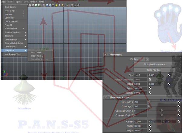
Upon entering my work area in preparation to start. I import my image of my door for the first time.
You are presented with four options of where to place your image.

• Perspective View
• Top View
• Front View
• Side View

Most of your work time will be spent in one of four views.
I always choose the front view as this gives me the best placing four my image.

• Setting up an Image

An image can be set on your image plane in placement and placement extras found within the attributes editor.
This can then be set to the size you need, for your project. This allows you to set up your image in the (X.Y.Z) axis of your work area. At this point I am ready to start my workflow in creation of my door.
Then I create my reference.

• Starting Workflow

Before starting my workflow I always created new shelf this allows me to access my tools more efficiently and quickly it depends on what project I’m doing.
Most common used tools are freeze transforms and delete by type history, these are two of the first tools I use on my new shelf in my work area.

    ·  Setting up an Image   

  
·         Shelf
                   
 
     · Demographical drawing  


I made my demographical drawing in sketch builder from Maya Autodesk using the application tools found within the programme.

The drawing its self was made in two parts the outer mainframe and the inner door which fits perfectly within its form.
The frame itself consists of 283 vertices each vertices fits on the corner of a polygon, polygon has four sides like a cube base but occupies a flat space which means it has no thickness to give a polygon thickness extrude the face this would then have six sides which means it would then have eight vertices, every time faces extruded the vertices go up by four.
My door frame has 563 edges and there are four edges to a polygon it also has 438 UV is and 558 potential tris.
A tris can only be achieved if a polygon flat plain is split from corner to corner this will then give two triangle polygons.
Trying to keep my door as simple as possible this would still make for a good game asset but less complicated to transport as a (DAX) file,
A (DAX) file is used to transport between programs it's primarily used by game engines this would be (UDK) or (Unit) this is a very similar game engine.

There are 13 full cubes to my door frame and several extruded faces to make up a very simple door frame.


   • Work Area

I always start my projects with, create polygon tool, this gives the best control on the size of my polygons in reference to my demographical drawing of my door.
This tool can be found in your workstation under mesh.
This tool allows me to create large sections of polygons in one go and allows you to create any shape you wish within the work area and gives you more control.

   • Retopology

There are several different software packages to do meet apology there would be 3-D cast Maya Autodesk, also my favourite set brush when you start Retopology on your model your model within Zbrush you need to load your hi Poly model first then you need to create csphere this will appear on canvass in your work area.
Next you need to activate your tools pallet also picking adaptive skin topology pallet also projection pallet.
Next you will select the rigging pallet first then your hi poly model in your work area once this is done you can then deactivate the rigging pallet then you are ready to click the edit Retopology button then begin laying down vertices.
The more vertices you add the better details, which will be transferred to the low topology version of your model.
With this done you might want to go to your transform pallet then activate symmetry in X.


      • UV Mapping


I laid out my UVs in the texture editor I then assigned the chequered pattern to the geometry of my doors UVs.
I did this in order to better see what is going on with my door.
When unfolding the UVs, it is recommended to use a repetitive pattern to best to see how to cope with the new UVs. I assigned a new lambert shader to the doors geometry and changing the texture resolution to (256 x 256). At this point I saved my workflow in preparation for cutting the UVs.
In order for the UVs, to be properly unfolded I first cut the UVs, in to shells, which will define the different parts of my door to be textured.
UV shells should be cut and unfolded so that they can lie flat without overlapping.
On highlighting my border edges and cutting the different parts of my shell you then have to stitch it back together, as the different parts are being stitched you must be careful when unfolding not to go over the border edge anything within the border can be unfolded safely and it will unfold inwards.
Going outside the border edge to unfold, it will make it unfold outwards this will distort the doors geometry.
After stitching the inner border edges together I then take a snap shot in the o to 1 plane in the most efficient way for my doors geometry.
Then exporting my UVs at a resolution of 1024.

      • The Colour Process


Painting in Photoshop to give my UVs colour and texture, then laying an ambient occlusion on the top.
This map was rendered using a custom shader node from mentalray, to give it shadow and depth, made in Maya Autodesk through the hypershade baking the texture to my geometry surface, then saving the texture at 2048 resolution gave me some nice detail for my UVs.
I was quite surprised to learn how many different techniques can be used for texturing.
Simple yet looks so complex when it is put altogether with all the techniques of Photoshop to UV mapping.
Next I used several translucent layers to build up the dirt rather than painting it straight onto the colour texture this gave it a more of a real look of battered metal, then added a chipped paint texture.
I use the same techniques on the door UVs, to give a rich texture.
Texturing can be done in several different ways you can use real high resolution photographs to apply a texture, but I wanted to give my door the more personal touch by painting by hand using pastoral colours
Putting all the maps together gave me a good finish on my door.
An important task for successful texturing is the creation of a texture library this holds true for professionals as well as independent students.
If I had chosen photographs as my textures I would best avoid a strong light within my scene.

So for my texture library, it’s created in Photoshop I use this as the basis for my texture.
So I keep all my painted textures at the highest resolution I can get.
Which then makes it easy enough to scale down to fit my geometry of my model? Adding a texture Blair to my painted affects makes it looks more real.
However using the painting texture tubes in Maya Autodesk is just as effective. But I get more control of my textures in Photoshop this suits me best.
Redefining and adding variables to my door.


     • Painting

     • Lighting

     • Colour theory and application

     • Anatomy

     • Set design

     • Shape and form

     • Light and shadow

     • Texture

     • Shape (2D) and Form (3D)

Form is three-dimensional (height, width, and depth) and includes simple objects like spheres, cubes, and pyramids for example, You will see that as a texture artist you are creating art on flat shapes, that are later placed on the surfaces of forms. An example can be seen in a common prop in many computer games.

When a shape is cut into a base material in Photoshop and some highlights and shadows are added, the illusion of form is created. A texture can be created rather quickly using this method.


 ·         UDK Screenshot  


My door is now a game ready asset and there is a lot still to learn about UDK transporting maps plugging them into the right coordinates so they appear on your door within the games workspace.

A UDK is a solid piece of technological; I’m still trying to learn as much as I can.

·         UDK Engine


The Start:


I started my process for my door with a simple box which I set out and mapped in Maya Autodesk.
Making sure I could get precise coordinates when doing my door, this also gave me time to think about the process of how I was going to achieve the look for my door that I wanted so in making the simple box it gave me a few good ideas watching the film aliens, this gave me the perfect setup for what I wanted in my door.
Those darks appealing feel that there was something sinister behind the door. To keep away from a to complex door, thinking of the time factor of a door that would look stunning under the right lighting and mapping conditions as they tell you in most of my Autodesk books setting the lighting is crucial it can make a bad door look good and vice versa.
preparation and setting out a good solid workflow for my door so this is why I did a normal box first to try and make some good lighting or to make a simple box look stunning in a plain environment while following a few basic rules which I applied within my workflow.